
Board-to-board connector in automotive vehicle electrical system architectures
Flight attendants of all types
Modern vehicle electrical systems are evolving, particularly due to the demands of e-mobility, autonomous driving, and 4K HD infotainment. board-to-board connector, with their specialized features, play a key role in managing this transformation to ensure high data rates with low latency.
As is well known, a vehicle’s vehicle electrical system is a complex network of electrical connections that links all electrical and electronic components. These include ECUs, sensors, actuators, lighting systems, infotainment, and connector.
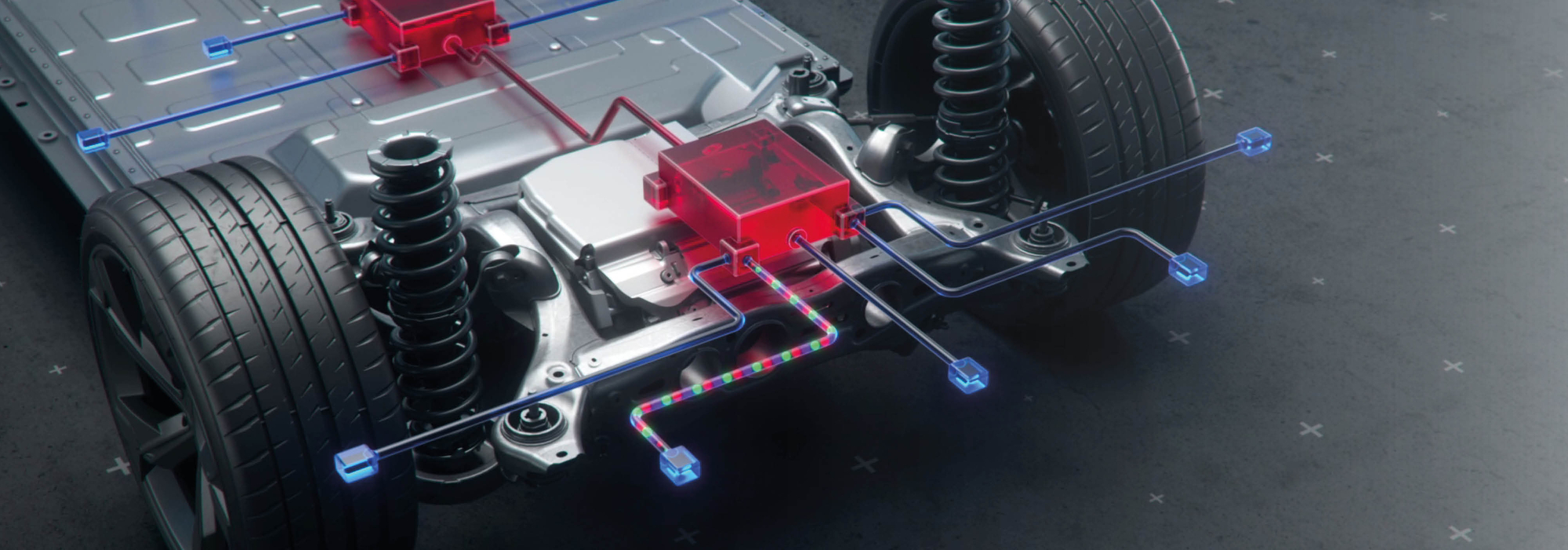
The three major trends in today’s automotive industry—automated, electric, and connected driving—require a fundamental change in the current electrical and electronic (E/E) architecture. This is because E/E architectures are evolving from a traditional, decentralized structure consisting of up to 100 ECUs toward a domain-based architecture in which ECUs are grouped into functional domains. Each domain has a coordinating high-performance computer (HPC), thereby reducing wiring and installation effort as well as costs and weight. A new development is the “zonal architecture” (zone architecture) in the vehicle, in which functions are bundled into a local zone controller, thereby reducing the number of ECUs and the complexity of the wiring.
The three major trends in today’s automotive industry—automated, electric, and connected driving—require a fundamental change in the current electrical and electronic (E/E) architecture. This is because E/E architectures are evolving from a traditional, decentralized structure consisting of up to 100 ECUs toward a domain-based architecture in which ECUs are grouped into functional domains. Each domain has a coordinating high-performance computer (HPC), thereby reducing wiring and installation effort as well as costs and weight. A new development is the “zonal architecture” (zone architecture) in the vehicle, in which functions are bundled into a local zone controller, thereby reducing the number of ECUs and the complexity of the wiring.


connector in the system architecture of vehicle electrical systems
Such structural changes also alter the challenges faced by a board-to-board connector that supports and implements these architectures. The task of transmitting significantly larger data streams and processing them into a comprehensive picture within an even more powerful ECU significantly changes the performance factors of the connector.
The responsibility for data transmission also extends to the various transmission technologies that must ensure sufficient bandwidth. These include:
The responsibility for data transmission also extends to the various transmission technologies that must ensure sufficient bandwidth. These include:
- LIN (Local Interconnect Network) as a very cost-effective technology for non-safety-critical and non-time-critical applications such as door locks, lights
- , or air conditioning (Controller Area Network) as the most widely used transmission technology for controlling the engine, transmission, starter, or for battery management systems
- FlexRay with a twisted-pair cable for data transmission for time- and/or safety-critical applications such as steering or brakes
- MOST (Media Oriented System Transport) as a fiber-optic cable for multimedia and infotainment systems
- Automotive Single Pair Ethernet (SPE) as a relatively new technology that is gaining increasing acceptance due
- to its bandwidth capacity SerDes (Serializer/Deserializer) for high-speed data transmission, ideal for cameras or displays
It is in the automotive industry’s interest to use as few different transmission technologies as possible in order to keep wiring complexity low. In this context, Automotive Ethernet plays a major role, although CAN (CAN FD and CAN XL), LIN, and SerDes are also relied upon. Key requirements for board-to-board connector can be derived from this, and the LV214 standard also provides insights into their characteristics.
High speed, EMC protection, as well as ruggedness and miniaturization

Due to sensor development and the E/E architecture presented, the data volumes to be transmitted are increasingly shifting toward high-speed transmission, which depends primarily on controlling the connector’s impedance. If this impedance fluctuates, resonances occur, which in turn result in signal transmission losses. Due to its geometry, a connector always poses a potential risk of impedance fluctuations, which are caused, among other things, by changes in material or geometry. This is
because impedance is determined by inductive and capacitive properties, which depend on the size, arrangement, and design of the pins. Changes in cross-sectional area, in particular, have a negative effect, which is why they must be minimized as much as possible. Furthermore, dielectrics (substances that are electrically weakly conductive or non-conductive) near the signal path can also have negative effects, which is why selecting the correct insulating material is equally important. In addition, there are also effects caused by coupling losses—the losses at the contact point between the blade and the spring. Finally, impedance fluctuations can be caused by protruding conductive elements that act as antennas. All these effects are summarized as insertion loss (the ratio of the outgoing signal to the incoming signal). In addition, there is return loss (return loss), which describes the ratio of the reflected signal to the signal to be transmitted.In light of the ongoing miniaturization of assemblies, EMC protection plays a particularly important role: This is because the high-frequency signals generated in this process are especially susceptible to interference from unwanted electromagnetic effects. Even the slightest interference is enough to cause significant distortion in data transmission, incorrect measurement signals from sensors, and inappropriate control commands—a scenario that is absolutely unacceptable from a safety perspective.
A shielded connector helps, because within an assembly, a connector always acts both as a sink for interference and as a source of interference. The component can also be disrupted by other components and, in turn, exerts an electromagnetic effect on surrounding components. shielding reduces both of these effects by a factor of approximately 100 to 200.

On the topic of robustness: Shock and vibration jeopardize the stability of data transmission just as much as chemical and thermal environmental influences caused by extreme temperatures, significant temperature fluctuations, corrosive gases, moisture, and dirt. The contact surface (contact surface) significantly determines the service life of the connector, because during operation, micro-movements occur between the two parts of the connector; over time, these lead to surface abrasion and thus to increased contact resistance (contact resistance), resulting in less effective signal transmission. A high-quality and durable contact coating (contact plating) helps minimize this surface abrasion.
In the contact system, a double-sided spring-loaded connector (Female) performs well, as it guarantees a contact point at all times, regardless of external influences. A “hermaphroditic” contact system offers even greater robustness, as the contacts interlock when plugged in, ensuring maximum contact reliability.
In the contact system, a double-sided spring-loaded connector (Female) performs well, as it guarantees a contact point at all times, regardless of external influences. A “hermaphroditic” contact system offers even greater robustness, as the contacts interlock when plugged in, ensuring maximum contact reliability.
One-piece connectors eliminate a vulnerable contact area, resulting in maximum resistance to external influences. The connection is made using the “press-fit technology” method, in which a press-fit pin (press-fit pin) is pressed into a through-hole (plated through hole (PTH)) in the circuit board, resulting in cold welding between the copper sleeve and the press-fit zone (press-fit zone). This creates a gas-tight, pottable connection to the circuit board that offers a failure failure rate ten times better than that of automatically soldered connectors (connector).

With limited installation space in automobiles, there is little room for sensors and ECUs, which in turn means that connectors must reduce their dimensions even further while maintaining the same or even higher performance. This is ideal for surface-mount technology (SMT), as—unlike press-fit technology—it enables a significantly smaller pitch as well as double-sided assembly of the printed circuit board.
The trend toward installing more and smaller connectors in assemblies results in longer tolerance chains, meaning connectors must compensate for increasingly larger tolerances during both assembly and operation. Connectors are already available that can absorb shocks and vibrations even more effectivelyconnector.
The trend toward installing more and smaller connectors in assemblies results in longer tolerance chains, meaning connectors must compensate for increasingly larger tolerances during both assembly and operation. Connectors are already available that can absorb shocks and vibrations even more effectivelyconnector.
Three suitable product families from ept

Zero8 products offer maximum scalability with customizable types, stack heights, and numbers of positions, supporting board-to-board distances from 6 to 21 mm and variable numbers of positions from 12 to 80. The connectors are mutually plug-compatible and freely combinable, with single- or double-sided shielding. The robust ScaleX connection technology ensures reliable contact under shock and vibration, compensates for tolerances, and provides EMC protection for a data rate of 16 Gbit/s.
Details on the Zero8
Details on the Zero8
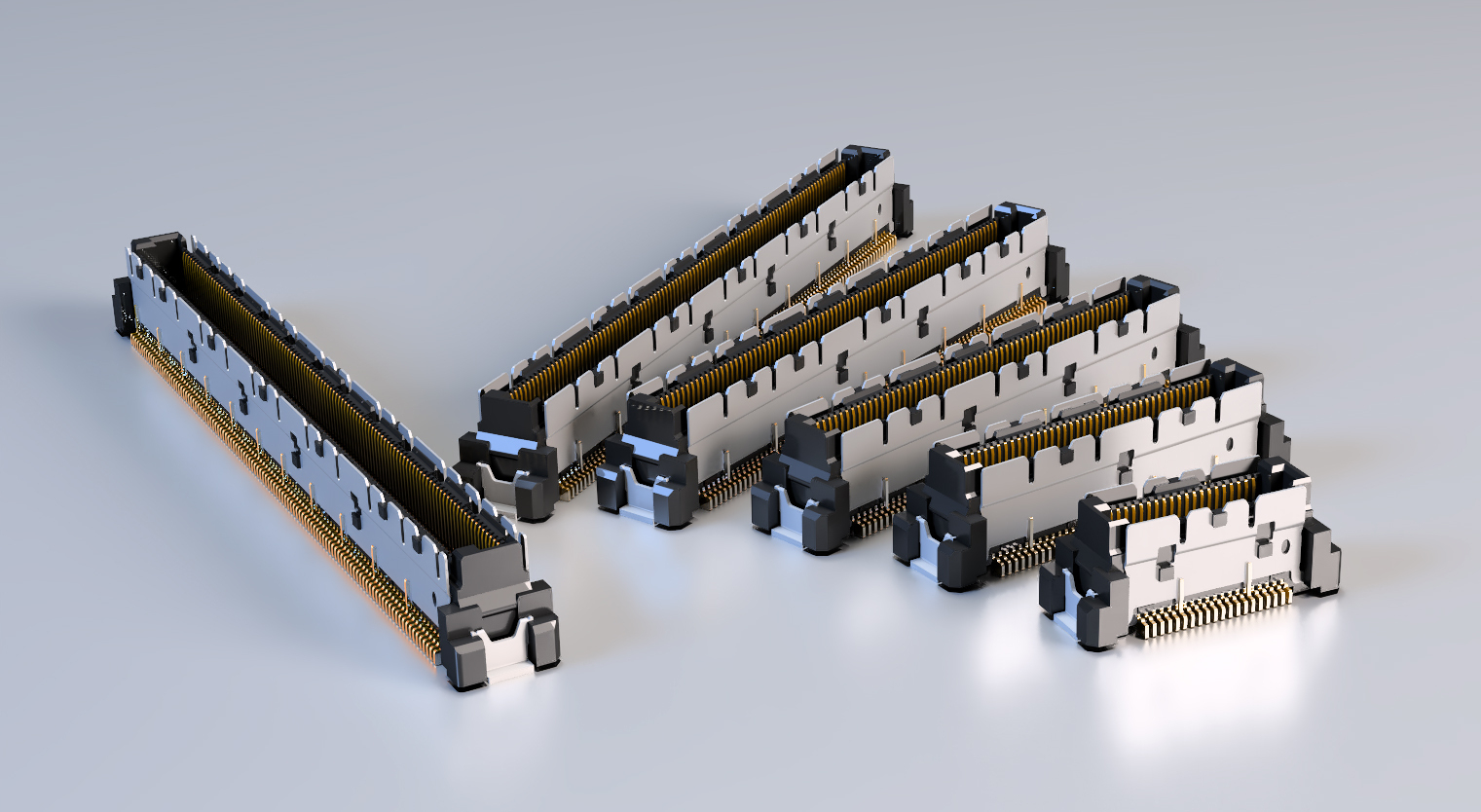
Colibri products are shielded, dual-row SMT-connector with a 0.5 mm pitch that are compatible with PICMG COM Express®, SFF-SIG CoreExpress®, and nano-ETXexpress. The receptacles for COM modules offer 196 signal pins and 24 ground pins, while the plugs for carrier boards are optionally available with guide posts, a shield, and SMT-mounting features. The Colibri COM Express system offers excellent signal integrity for data rates exceeding 25 Gbit/s, making it ideal for high-speed applications with limited installation space.
Details on Colibri
Details on Colibri
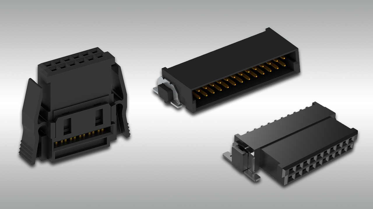
As a third product family, One27 offers robust and compact PCB connections in SMT with a pitch of 1.27 mm. They support board-to-board distances from 8 to 20 mm and are available with 12 to 80 contacts as well as in cable assembly. Both parallel and right-angle connections are possible; they are particularly robust and easy to process, ensuring reliable contact and high flexibility in PCB layout.
Details on One27
Details on One27

Looking ahead, autonomous driving will be closely linked to the further development of data transfer and communication technologies. Key aspects such as 5G connectivity, cybersecurity, V2X communication, as well as edge computing and blockchain technology will significantly shape data transmission, but one thing remains certain: the coexistence of vehicle electrical systems and connectors will eventually make a car without a steering wheel a reality.
Are you looking for a specific connector?
product list

Any questions?
Then please contact us!
Submit an inquiry via the form
+1 (806) 304-0402
sales@eptusa.com
Then please contact us!
Submit an inquiry via the form
+1 (806) 304-0402
sales@eptusa.com