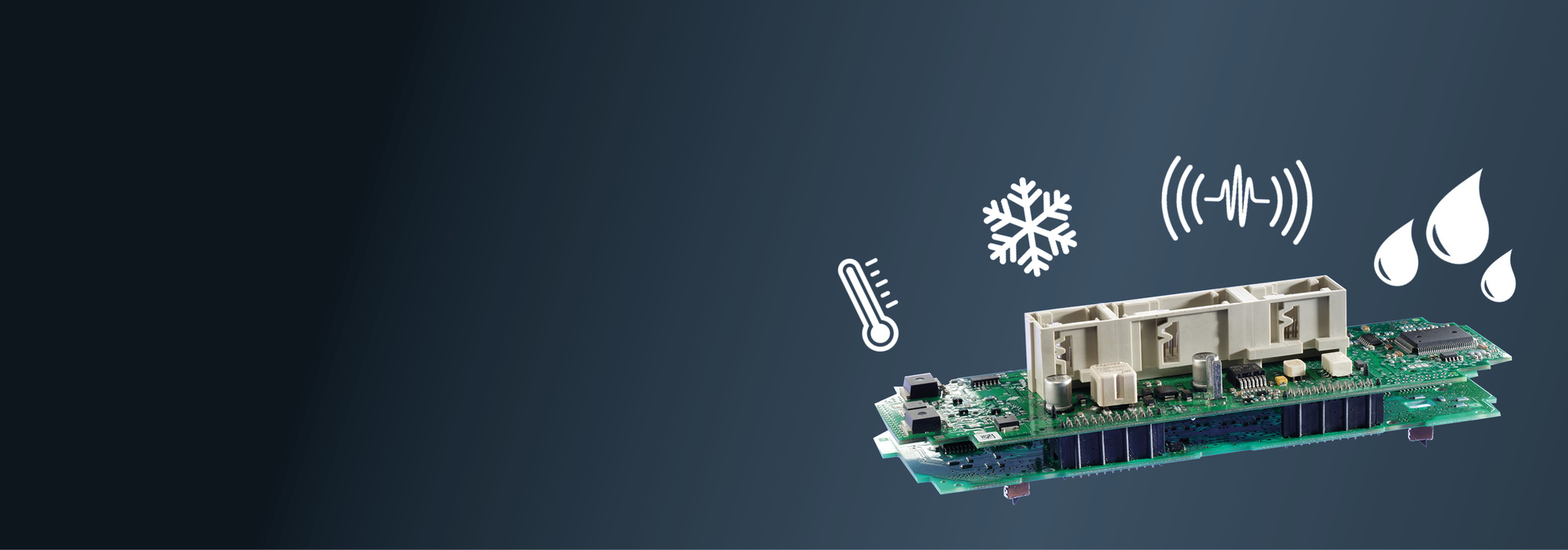
Whitepaper: How Board-to-Board Connectors are Made Robust and Which Influencing Factors Affect the Connector
Whether used in the fields of aerospace, industrial automation, transportation, or healthcare, board-to-board connectors must always guarantee reliable signal transmission and must not fail under any circumstances. At the same time, they are exposed to wide range of stressors from their environment: Mechanical effects, such as shock, vibration, and oscillations endanger the stability of the data transfer rate, as do thermal and chemical environmental influences caused by extreme temperatures, strong temperature fluctuations, corrosive gases, moisture, and dirt. Manufacturers of high-quality PCB connectors therefore pull out all the stops to arm their board-to-board connectors with the means to withstand these stressors.
Board-to-board Connectors – Robustness Despite Miniaturization
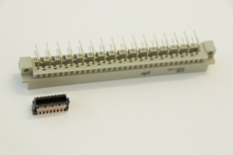
The field of modern electrical engineering is subject to one trend more than ever: miniaturization. Assemblies and their components must not only become increasingly more powerful, but they must also become increasingly smaller. Nevertheless, they are often used in harsh real-world conditions. Components as well as connectors are therefore becoming more and more delicate, while the amount of stress placed on them remains the same. However, a high-quality connector resists this stress not only as well as its older and bigger predecessor, but even better. This is due to further developments in material composition as well as in product design, such as further developments in the geometry of insulator material.
A wide range of influencing factors affects the robustness of a board-to-board connector:
A wide range of influencing factors affects the robustness of a board-to-board connector:
- Surface
- Contact design
- Contact system
- Termination technology
- Insulator material design
- Tolerance range
Influencing Factor – Surface
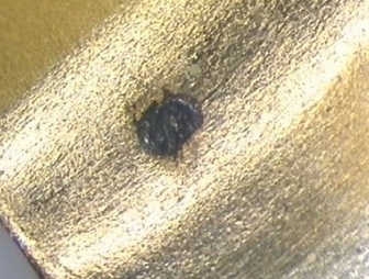
One influencing factor is the plating. This largely determines the durability of the connector, which is usually measured in mating cycles. When used in the field, the connector is subject to certain micromovements. These lead to abrasions and, as a result, oxide formation. The consequence is an increased level of contact resistance and therefore poorer signal transmission quality.
A high-quality and durable contact coating is therefore decisive as regards surface abrasion.
Read our whitepaper free of charge to find out what to look for when choosing the plating.
A high-quality and durable contact coating is therefore decisive as regards surface abrasion.
Read our whitepaper free of charge to find out what to look for when choosing the plating.
Influencing Factor – Contact Design
The contacts of a PCB connector are stamped or turned using a CNC machine. When stamped, however, an inhomogeneous, sharp-edged surface that is visible under a microscope is produced on the underside of the stamped strip of material. Conventional systems make contact on this stamped edge, which entails an increased level of surface abrasion and therefore a higher degree of contact resistance.
Free Whitepaper on the Robustness of a Connector

Read our whitepaper free of charge to learn about how to create the lowest possible contact resistance by choosing the right contact design and more. We also explain how board-to-board connectors are made robust and what exactly needs to be taken into account, based on various influencing factors.
Request free whitpaper »
Request free whitpaper »
Influencing factor – Contact System
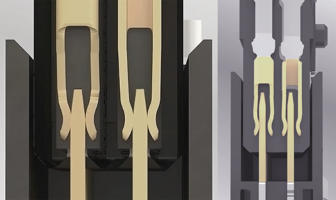
Traditional two-piece connectors have one male contact and one female contact. However, in the event of strong shock, the male connector may lift off of the female connector. To prevent such an interruption of contact, a double-sided female connector can be used to provide redundancy and thus contact reliability, as the second female contact ensures signal transmission at all times via at least one contact point.
Connectors with a “gender-neutral” contact system, on the other hand, are even more robust. The special feature here is the identical contact geometries of the connector halves.
Connectors with a “gender-neutral” contact system, on the other hand, are even more robust. The special feature here is the identical contact geometries of the connector halves.
Influencing Factor – Termination Technology
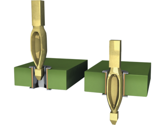
There are several ways to attach connectors to PCBs.
One of these is to use the previously mentioned press-fit technology. The aim of this technology is to achieve the greatest possible retention forces between the connector and the PCB using the least possible amount of press-fit force. The retention forces are decisive for the mechanical connection, which in turn must withstand shock and vibration.
However, press-fit technology is not always suitable, for example, if PCBs are to be assembled on both sides, or if the minimum distance to components in the direction of force cannot be maintained. Surface-mount technology (SMT) is another way to create a reliable and durable connection between the connector and the PCB. Solder paste is used to solder the connectors onto the PCB’s specified connection surfaces: the solder pads.
Influencing Factor – Insulator Material Design
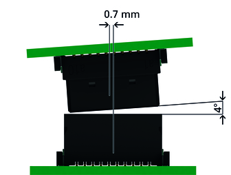
The geometry of a board-to-board connector’s insulator material also helps protect the contacts from being damaged during operation or assembly. It should be designed in such a way that the vulnerable contacts inside the connector are protected.
In addition, inclined insertion surfaces can prevent damage during assembly. They help to compensate for misalignment of the PCBs when mating in any direction. By using an additional capture range, the two connector halves can be plugged together without damage even in the event of a center or angle offset.
In addition, inclined insertion surfaces can prevent damage during assembly. They help to compensate for misalignment of the PCBs when mating in any direction. By using an additional capture range, the two connector halves can be plugged together without damage even in the event of a center or angle offset.
Influencing Factor – Tolerance Range
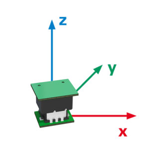
The tolerance range of a connector plays a decisive role in assessing its robustness. Mechanical movements will lead to wear or even damage to the connector if the connector cannot compensate for given tolerances.
In the field, for example, loads are generated not only in the X and Y directions, but also in the Z direction. This raises the question of whether a connector’s mating is absolutely secure. Absolutely secure mating describes the overlap area of the male and female connectors and allows not only different board-to-board distances but – depending on the size of this area – different tolerance ranges as well.
Read our whitepaper free of charge to find out what other factors influence the tolerance range and how to compensate for them.
Request free whitepaper »
Test Methods
There are various test methods for thoroughly testing board-to-board connectors in terms of their robustness. Variables such as dielectric strength and contact resistance are each considered before and after a load test, and the condition of the contacts is inspected visually. For example, the effects of 500 mating cycles on the connector’s dielectric strength can be tested, or a climatic test can be performed to determine whether several hours at first -55°C and then 125°C have a negative effect on the connector’s contact resistance. When performing the temperature shock test, the connector must withstand the rapid fluctuation between these extreme temperatures 100 times for 30 minutes each. The center offset and angle offset during mating, as well as the tolerance range in the mated state, should also not only be checked in theory on the CAD model but should be extensively tested in practice, and the load capacity should be confirmed empirically. It is equally important that different tests that are of critical importance to the plating be performed in combination in order to simulate real conditions. For example, mating cycle tests and corrosive gas tests could be performed in combination to ensure that the connector’s performance in terms of contact resistance and dielectric strength has not deteriorated and that the contacts have not been damaged.
Free Webinar on the Robustness of Board-to-board Connectors

Do you need detailed knowledge of how to choose suitable connection technology based on your requirements?
Then set up an appointment with us for a free webinar.
Request webinar »
Then set up an appointment with us for a free webinar.
Request webinar »
Your Design – Your Choice
There are different robustness criteria that a board-to-board connector must meet depending on the requirements of the application. For example, does it have to compensate for high tolerances? Is it subjected to large shock loads or vibrations? Is it used in environments exposed to intense heat or cold? Or does the connection solution need to be protected from moisture, corrosive gases, or dirt? If a user uses these questions as guidance when selecting their connection solution, they can be sure that their connector is perfectly equipped for use in the field.

Questions?contact us!
contact form


