
The Inverter in electromobility applications and connector requirements
Power Management and intelligent power supply
Battery management systems and power electronics play a key role in electromobility because they connect different components in electric vehicles. Connectors are what provide the connection function within inverters. These are needed to control and transmit signals, data, and high currents reliably, safely, quickly, and without losses despite demanding operating conditions. To do this, the connectors have to meet a number of requirements in terms of temperature resistance, compactness, and flexibility, as well as performance and robustness.
Background: The electromobility transition
The automotive industry has experienced a shift toward electromobility in recent years.
This shift is evidenced by the increased production of electric vehicles (EVs), the uptick in sales, and the expansion of the charging structure for EVs. Consumer demand for more sustainable transportation options is constantly growing. By the same token, heavy investments have been made in battery technology in order to make progress in terms of the range, performance, and cost of electric vehicles. Government incentives for EV adaptation, automotive manufacturers’ commitments to phase out the internal combustion engine, and stricter emission standards continue to add momentum to the transition toward electromobility.
As a result, traditional automakers are increasing the production of electric vehicles.
The inverter in electric vehicles
Inverters in electric vehicles are responsible for intelligent power supply and energy management. They connect the EV’s battery with the vehicle’s electrical components and, during the charging process, also with the public power grid. This requires different voltage levels.
There are mainly two types of inverters used in electric vehicles: DC-DC inverters and AC-DC inverters. DC-DC inverters change the voltage of a direct current. AC-DC inverters (rectifiers) change direct current into alternating current or vice versa. Inverters therefore convert the electrical energy into the voltage level and form required for the electrical component in question in order to ensure optimal performance.
Accordingly, inverters ensure efficient transmission between the battery and the electric motor in electric vehicles in order to guarantee the longest possible range. Moreover, inverters have to fulfill various protective functions to protect the electric vehicle and its components against overloading, overvoltage, and overheating. Inverters ultimately help ensure that electric vehicles operate safely, efficiently, and reliably while achieving a level of high performance.
Inverter requirements
Inverters have to meet all kinds of requirements. This includes compatibility, integrability, and efficiency. This means that the inverters have to be compatible with other systems in the electric vehicle, such as the battery, electric motor, and control unit. Inverters must also be easy to integrate in order to simplify the electric vehicle’s design and save time and costs. In addition, high efficiency is essential for enabling long ranges.
Reliability, cost-effectiveness, and overload protection must also be provided. Reliable functionality is required in order to guarantee stable operation for safe and uninterrupted driving. Inverters have to be affordable in terms of the electric vehicle’s efficiency requirements. They also have to be equipped with overload protection to prevent overload and overvoltage and protect the electric vehicle and its components.
In terms of technical requirements, temperature resistance, compactness, performance, and robustness play a pivotal role. For example, the inverter has to:
- operate in a wide range of temperatures and be stable in order to be used in a vehicle
- be space-saving and lightweight, as any additional weight reduces the EV’s range
- demonstrate a high level of performance in terms of transmitting power and data in order to meet the needs of the electric motor and other systems
- be resistant to environmental influences, shock, and vibrations in both the installation and assembly process as well as for automatic mating and during operation
Looking for a specific connector?
product list
Connector system requirements
Inverters connect the different vehicle components, such as the battery storage unit, with the electric motor. Inverters have to meet the requirements listed above in order to transmit the data and currents reliably and in real time.
Connectors are what provide the connection function between the PCBs within inverters. The connectors should transmit the signals, data, and currents reliably, safely, quickly, and without losses despite demanding environmental conditions. Therefore, comparable quality requirements apply to the connectors.
Connectors are what provide the connection function between the PCBs within inverters. The connectors should transmit the signals, data, and currents reliably, safely, quickly, and without losses despite demanding environmental conditions. Therefore, comparable quality requirements apply to the connectors.
Temperature resistance
The materials the connectors are made of should withstand high temperatures because the vehicle’s internal operating conditions demand it. There are a wide range of synthetic materials to choose from for the insulator material when selecting the right connector. That being said, LCPs (liquid crystal polymers) possess exceptional properties in this regard. LCP insulator material is impressive because it features exceptional dimensional as well as thermal stability, a high level of rigidity – even with thin-walled components – and a low coefficient of linear thermal expansion. The UL 94 V-0 flammability rating results in an operating temperature range of -55°C to +125°C for connectors with LCP insulator material.
Compactness and flexibility

Connectors that have a small pitch are very well suited for use in inverters, as they save space, require minimal installation space on the PCB, and thus meet the requirement for compactness. This is why systems with a pitch of 1.27 mm, 0.8 mm, or 0.5 mm, for example, are used. But not only should the connectors be small, they should also have the ability to adapt to the widest range of requirements. This concerns things such as the required heights, numbers of pins, or PCB configurations. When it comes to connectors such as those in ept’s One27 product range, the wide variety of different connector types offered make it possible to connect PCBs in parallel, horizontally, or perpendicularly and to connect ribbon cables to the PCB.
The right contact system:
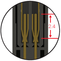
ept’s One27 connectors enable continuous realization of horizontal PCB clearances of 8 mm to up to 20 mm. This is made possible by the design of the mating face, which features an overlapping contact of 2.4 mm. Using a cable connection makes it possible to compensate for tolerances in all directions and implement the PCB clearances required in individual cases, depending on the application.
More information about the product here:
One27 »
Performance
Good signal integrity properties, which are responsible for the quality of the data transfer rate from transmitter to receiver, as well as for protecting the signals, are a basic requirement for use in inverters. This is because the data transmitted by the connector is used to enable the inverter to transmit data to the coupled electrical components intelligently and in real time.
The quality of the data transfer rate depends on three criteria:
The quality of the data transfer rate depends on three criteria:
- The impedance curve: The signal is reflected as soon as the impedance in the transmission path changes. This degrades the quality of the data transfer rate. Even a change in material or geometry can cause the impedance to fluctuate.
- The insertion loss: This parameter helps evaluate whether the receiver can clearly identify a signal along the entire transmission path.
- If a typical insertion loss value of -3 dB for a Zero8 connector from ept (SMT connector with a pitch of 0.8 mm featuring ScaleX technology) is taken as a criterion for the data rate, this results in a transmission speed of at least 16 Gbps at 8 GHz.
- The crosstalk during signal transmission: Crosstalk is the unwanted influence of a signal by a signal on another wire, whereby a distinction is made between near-end and far-end crosstalk depending on the type of influence. The strength of the crosstalk depends greatly on the signal assignment and the ground assignment.
A connector’s signal integrity properties can be significantly improved by using EMC (electromagnetic compatibility) protection. Electromagnetic compatibility means the ability of a technical device not to be disturbed by intentional and unintentional electrical or electromagnetic effects and its ability not to disturb others. Electromagnetic interference in connectors can be reduced by using a shielding concept. The coupling inductance simulates the connector both as a source of interference and as an interference sink. The effect of the shielding concept can be clearly seen in the figure below by looking at the colored curves and the values of the coupling inductance.
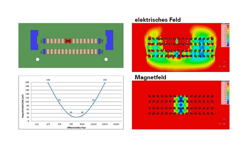
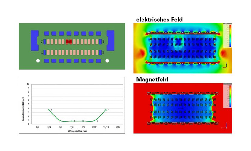
Sources of interference and interference sinks can be positioned closer to each other on the PCB when using the shielded Zero8 connector. This also makes it possible to achieve a higher performance rating when the electrical device is subjected to the prescribed burst and surge tests.
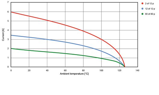
In addition to signal integrity properties, a connector’s current carrying capacity in terms of transmitting power also constitutes an important core property. Current-carrying capacity curves can be used to determine how much current may be passed through a contact at a given ambient temperature in order not to exceed the maximum permissible limit temperature of the component. The following derating curve shows an example of how different current specifications per contact result for the Zero8 connector depending on the number of pins and the number of current carrying contacts.
As can be seen in the figure, a connector with 12 pins (blue curve) achieves better current carrying capacity than a connector with 80 pins (green curve). The reason for this is that there are fewer hot spots forming inside connectors with a small number of pins. Less heat is generated here and it can be better distributed. Heat is dissipated even better if the current is only conducted via a small number of the contacts (red curve).
As can be seen in the figure, a connector with 12 pins (blue curve) achieves better current carrying capacity than a connector with 80 pins (green curve). The reason for this is that there are fewer hot spots forming inside connectors with a small number of pins. Less heat is generated here and it can be better distributed. Heat is dissipated even better if the current is only conducted via a small number of the contacts (red curve).
Robustness
In the case of SMT connectors, a connector’s robustness can be seen in things such as the layout of the contact between male and female connectors with double contacting, the quality of the contact coating for low surface abrasion, or the solder feet, which must be designed for optimal meniscus formation. SMT connectors often need to be as rugged as possible when they are being processed and handled, too. During mating itself, inclined insertion surfaces and a generously designed capture range enable a high degree of tolerance compensation and serve to make handling connectors as easy as possible.
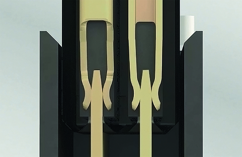
Connectors in an inverter are exposed to high levels of shock and vibration because they are usually installed close to the motor. Shock and vibration can impair the constant, uninterrupted contact that must be maintained between two connectors, or one connector and the PCB. Reliable, stable contact between a connector and the PCB can be achieved using press-fit technology. The aim of press-fit technology is to achieve the highest possible retention forces between the connector and the PCB. This is because the retention forces are decisive for the mechanical connection, which in turn must withstand shock and vibration. This termination technology is a proven process in which a press-fit pin is pressed into a PCB hole and a gas-tight, corrosion-free, low-resistance, and electrically safe mechanical connection that is also suitable for potting is produced by mechanically deforming the pin. ept GmbH offers catalog products as well as customer specific solutions that feature this processing technology.
ith this process, the press-fit pin has a larger diagonal than the diameter of the PCB hole. The connector pin in the press-fit zone is flexible so that the PCB is not deformed or damaged by the physical forces exerted during the press-fit process. The deformation is therefore limited to the press-in zone. During the press-fit process, a cold weld is formed between the contact pin and the metallized PCB hole, which gives the connection a high degree of mechanical robustness without subjecting the PCB to a thermally stressing soldering process. It is also specified in DIN EN 60352-5 and remains contact-safe and stable even under very high mechanical and thermal loads, such as vibration, bending, and severe temperature changes, and can withstand shock loads of up to 200 g. The Flexilink connector from ept is characterized by special quality features due its press-fit technology:
ith this process, the press-fit pin has a larger diagonal than the diameter of the PCB hole. The connector pin in the press-fit zone is flexible so that the PCB is not deformed or damaged by the physical forces exerted during the press-fit process. The deformation is therefore limited to the press-in zone. During the press-fit process, a cold weld is formed between the contact pin and the metallized PCB hole, which gives the connection a high degree of mechanical robustness without subjecting the PCB to a thermally stressing soldering process. It is also specified in DIN EN 60352-5 and remains contact-safe and stable even under very high mechanical and thermal loads, such as vibration, bending, and severe temperature changes, and can withstand shock loads of up to 200 g. The Flexilink connector from ept is characterized by special quality features due its press-fit technology:
- Low jet effect (that is, deformation of the circuit path)
- Avoidance of cold solder joints and short circuits by means of solder bridges
- High level of strength and robustness combined with excellent female contact properties
- Reliable processability due optimal processing technology calibration
- Reliable reproducibility in production due to its molded design
- Fulfillment of the highest requirements of leading automotive electronics manufacturers
- The highest degree of reliability and protection against malfunction proven a billion times over